Discussion on non-reacting flow field / mixture fraction
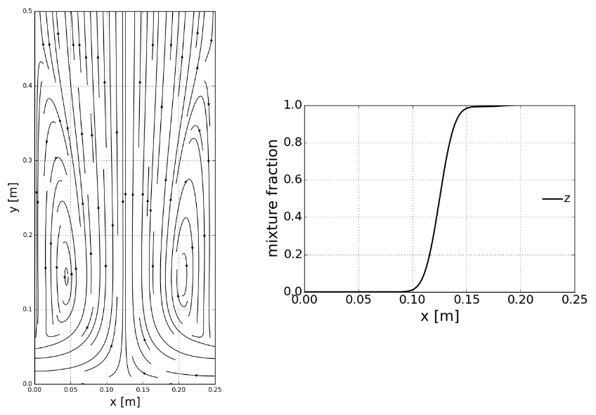
Following figure is showing the flow feature of the counter flow made by two fuel and oxidizer streams with Re=100. The shape of streamlines makes perfect symmetry and stagnation point at the center axis. Two vortices are formed at both side walls.
The figure on the right side describes the mixture fraction distribution along the centerline axis of the fuel and oxidizer streams. As well known, the mixture fraction goes from 0 of pure oxdizer to 1 of pure fuel jet. The significant mixture is noticeably formed at the center position.
- Steady flow streamline and mixture fraction distribution along the centerline axis
- Mixture temperature and mass fraction of fuel and oxidizer in the mixture fraction space (up) and physcal space (bottom)

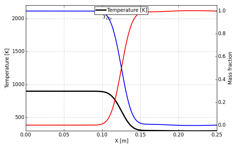
Both two figure above illustrates the mixture temperature and mass fractions of two non-reactive streams along the \(z\) space and \(x\) space. In mixture fraction space, all the mixture temperature and mass fraction draw linear lines, meaning linear composition of mixture is made. As already assumed in the previous section, the thermal properties is constant and so the temperature is also an outcome of linear mixture of two reactants.
If the mixture field lies on the spatial axis, the noticeable curve of the mixture fields is made in the region where the mixture fraction \(z\) changes as illustrated previously. Since the density and diffusivity of two streams are assumed identical to each other, exactly half of each mixture fraction is located at the stagnation point.